Modern adjustment for a classic Ground Plane
28 Jan 2015
One antenna that Elmers always recommend that newly licensed hams build is the simple solid copper wire ground plane, among others. It is so popular that there are probably as many websites depicting the various types as there are new hams this year. This has been a staple of the base station low power setups for a very long time. It is small, simple and easy to make yourself. Its popularity is something that has some new hams possibly wondering why, and many times the experienced hams answer is something more along the lines of "it just works well". Even if they try to get technical, sometimes the experienced hams may still not entirely understand why it works so well. I myself do not have years of college or decades in the field so I may not completely understand the electromagnetic process, but what I do understand is computers. With a computer in front of me and some modeling software, here I come along to throw a kink in the process, so all hams, new and old should enjoy this.
I am modeling these for the 2m band, so other bands will very likely need their own adjustments or the alterations for 2m may not work for say 10m. When I run my calculations, I also tend to run it over real ground, typically 30 ft up in the air (10m) and isolated from the tower. Because of this, the gain numbers may appear inflated over other calculations that make use of "free space" option. I prefer real ground because almost never in the real world do we actually have an antenna up in free space free from any other obstructions.
First is the standard ground plane antenna with the horizontal ground radials, making for an actual proper flat ground plane that some seem to love. With the radial at 1/4 wavelength, using copper wire for the radiator and radials, and a common load in the middle to allow for a dual band antenna (2m/70cm), at 146MHz it comes back with 24.72 Ohms, 2.41:1 SWR, and 6.26dBi at 2.7° above horizon. Not very promising numbers for use with 50 Ohm coax. Same setup at 444MHz comes back with 59.75 Ohms, 2.0:1 SWR, and 5.88dBi at 42.8° above horizon, but the useful radiation towards the horizon (0-10°) shows negative gain, so you would need more power to overcome the reduced gain.
Second is the standard ground plane antenna with the ground radials dropped down 45° below center horizontal plane. This 45° "drop" has long been the recommendation for VHF antennas to bring the resistances closer to the 50 Ohm coax used by most hams, and for the most part it does get it much closer, although still not perfect. Running the same calculations with copper wire, 10m above real ground, run at 146MHz, it returns these numbers: 58.62 Ohms, 1.44:1 SWR, and 6.55dBi at 2.7° above horizon. This same setup run at 444MHz: 50.55 Ohms, 1.03:1 SWR and 3.93dBi at 57.0° above horizon. In both cases the resistance is much closer to the expected 50 Ohm coax over the horizontal ground plane version above, SWR is much more under control, and slightly more gain for 2m. It also has the benefit of slightly more usable gain closer to the horizon for 70cm, but the majority of the signal is still going way up in the air as shown by the "3.93dBi at 57.0° above horizon". The resistance for 70cm is under control, although for 2m, the +8.62 Ohms wile close enough for most people, it may not be close enough for some.
So while both of these types do show some promising numbers and have been in use for many years, I was on the hunt for ways to bring these numbers in closer to the preferred resistance and SWR. While 58.62 Ohms and 1.44:1 SWR is acceptable in most cases, most of us want to bring it down closer to 1:1. Thus comes in the optimization process to help level the resistance closer to 50 Ohms, low SWR and spit out the adjusted antenna. For the horizontal ground plane, all it did was adjust the numbers slightly to return much better numbers: The vertical radiator comes back as 0.49m or 19.291 inches long, with the radials at 21.69" and 19.68". What it did was have 2 radials across from each other with matching lengths, so the 2 radials along X were 19.68" long, and the 2 ground radials along Y are 21.69". Now compare the numbers:
- 2m:
- Original: 24.72 Ohms, 2.41:1 SWR, and 6.26dBi at 2.7° above horizon
- Optimized: 49.59 Ohms, 1.01:1 SWR, and 8.37dBi at 2.7° above horizon
- 70cm:
- Original: 59.75 Ohms, 2.0:1 SWR, and 5.88dBi at 42.8° above horizon
- Optimized: 58.04 Ohms, 1.17:1 SWR, and 5.29dBi at 54.8° above horizon
So just with a slight adjustment of the lengths of the ground plane radials, it leveled the resistance so a balun should not be needed, it brought down the SWR, and boosted the gain by over 2dBi. I ran the same alteration process through the "optimizer" and for the angled ground plane version, the resulting antenna was actually quite different from what we started with, and also produced some very interesting results. First let me show you the wire frame of the antenna itself:
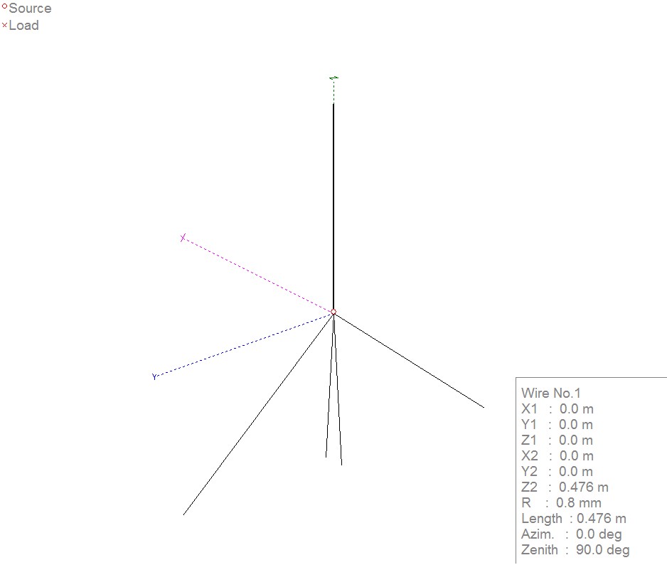
The primary alteration seen is the 2 shortened radials brought in and swung down from the center. The lengths are: 18.74" vertical radiator, 20.787" long ground radials angled down 45°, and 13.268" short radials angled down approximately 80-85°. Running the same process as above with copper wire, 10m over real ground:
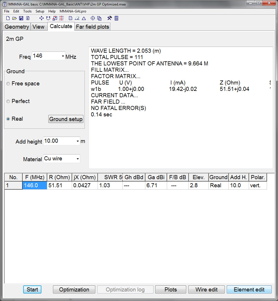
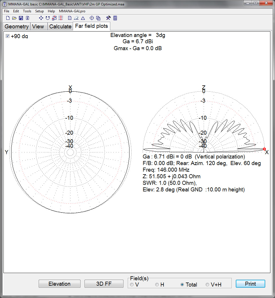
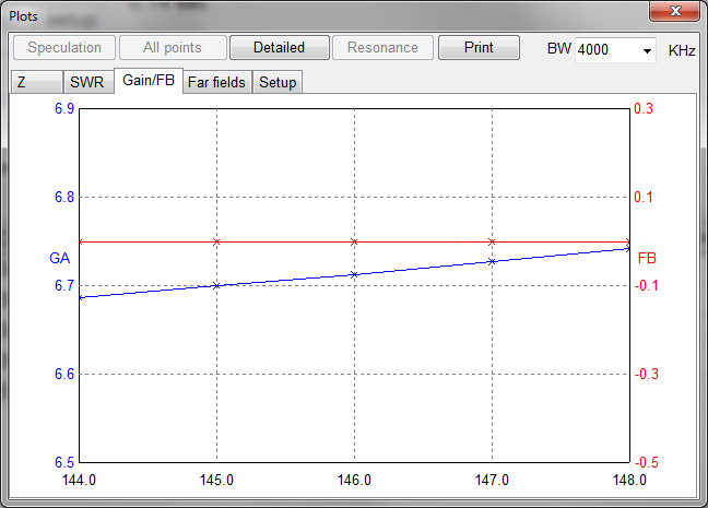
Here we see the numbers have adjusted quite favorably: 51.51 Ohms, 1.03:1 SWR, and 6.71dBi gain at 2.8° elevation. Comparing with the above "standard" GP with angled ground plane: 58.62 Ohms, 1.44:1 SWR, and 6.55dBi at 2.7° above horizon, we see the resistance at +1.51 instead of +8.62, SWR much lower, and even a slight gain bump. Granted that 0.15dB will not be seen or recognized by anyone listening, it should come in as a cleaner signal with the Ohms close to 50, and SWR lowered. Another minor mention as seen by the plot below is there is a very slight directionality to this altered GP, favoring the longer ground radials. Looking from the side, it has 6.71dBi gain at 2.8° above horizon, but looking down from above, it has this gain in the direction of the longer radials (along X, or for example north and south), with 6.2dBi 90° off (from the shorter radials along Y, or for example east and west). For some of us this can be used to our advantage, to point the longer ground radial sides towards distant repeaters and/or the lower gain side towards nearby local repeaters.
Here we see the plots with most of the signal going out close to the horizon:
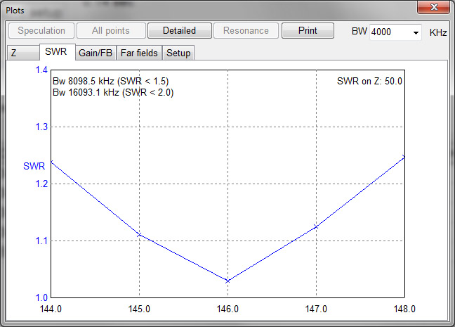
Then the SWR and gain lines:
So how does this work in the real world? I just put mine up a few days ago and so far getting good signal reports from others, it seems to verify that it has good gain and clean signal reports. I was only able to run one informal test to compare it to my current copper pipe Jpole, but the signal report back seems to favor this ground plane but only by a small margin (which I suspect relates to the bandwidth of the large diameter copper pipe versus the small diameter 12ga copper wire).
So this is still a process in the works and I hope to get some equipment from an elmer to verify some real world numbers, and how it corresponds to the computer calculated numbers, so stay tuned over the next few months.
Take care and 73s!
KM4FMK
As more blog entries are added, some get moved to the archived blog entries page. As this is a new website, this will probably not need to be done for a month or two.